What Is Fault Loop Impedance? Formula, Disconnection Times & AS/NZS 3000 Compliance
12Feb
Ahmed Tayeh
Standards & Compliance, Cable Sizing
What Is Fault Loop Impedance? Formula, Disconnection Times & AS/NZS 3000 Compliance
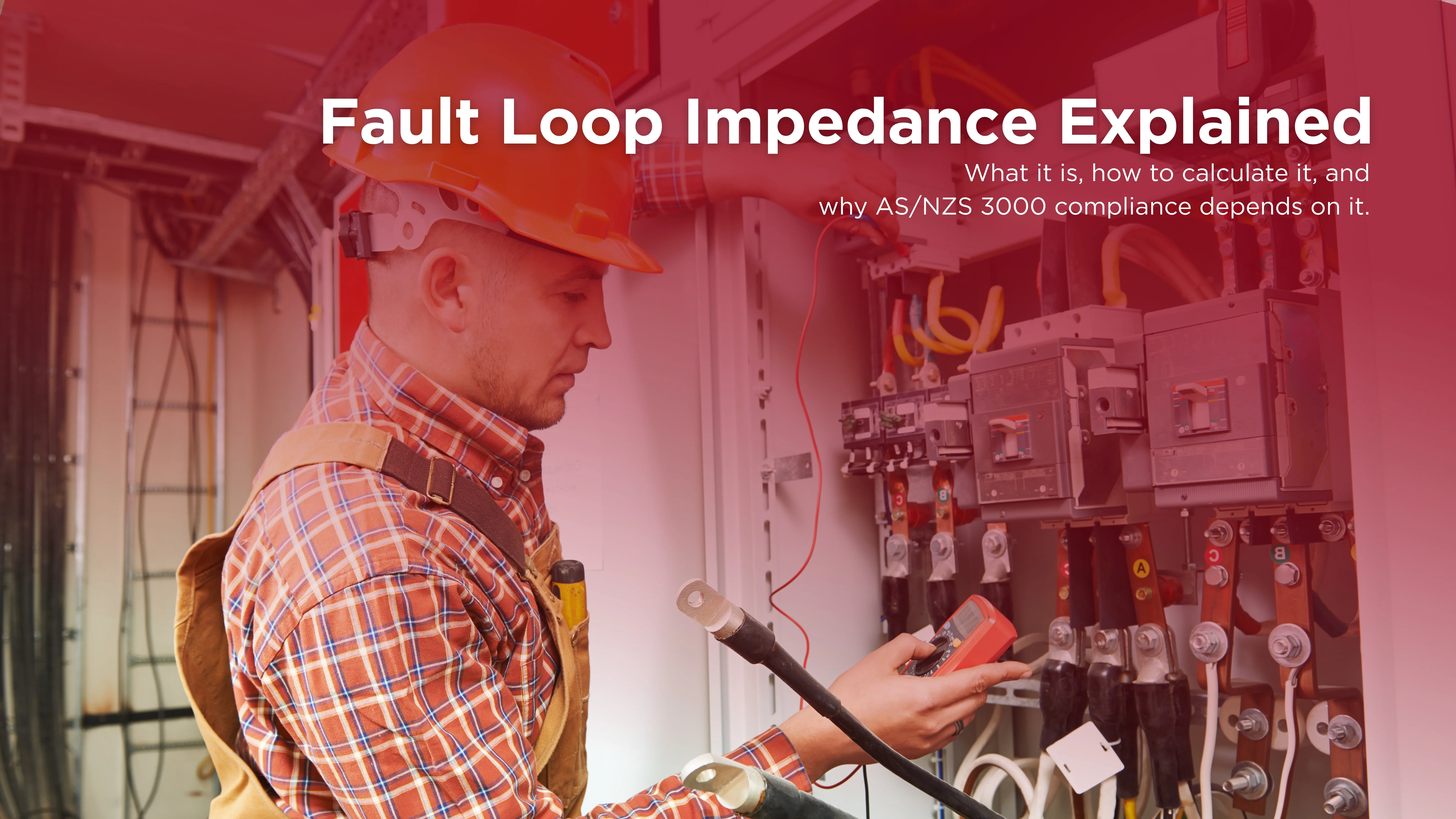
Electrical installations in Australia have a single safety requirement: when a fault occurs, the protective device must disconnect the circuit fast enough to prevent a lethal electric shock. Whether that protective device trips in 0.4 seconds or takes too long to operate at all depends almost entirely on one value: the fault loop impedance. If you're designing, installing, or certifying electrical systems in Australia, fault loop impedance is not a theoretical concept. It's the number that determines whether your protective devices will actually protect people, and whether your installation will pass compliance. This guide covers everything you need to know: what fault loop impedance is, how the loop is constructed, how to calculate it, what AS/NZS 3000 requires, and how to test it correctly on site.
What Is Fault Loop Impedance?
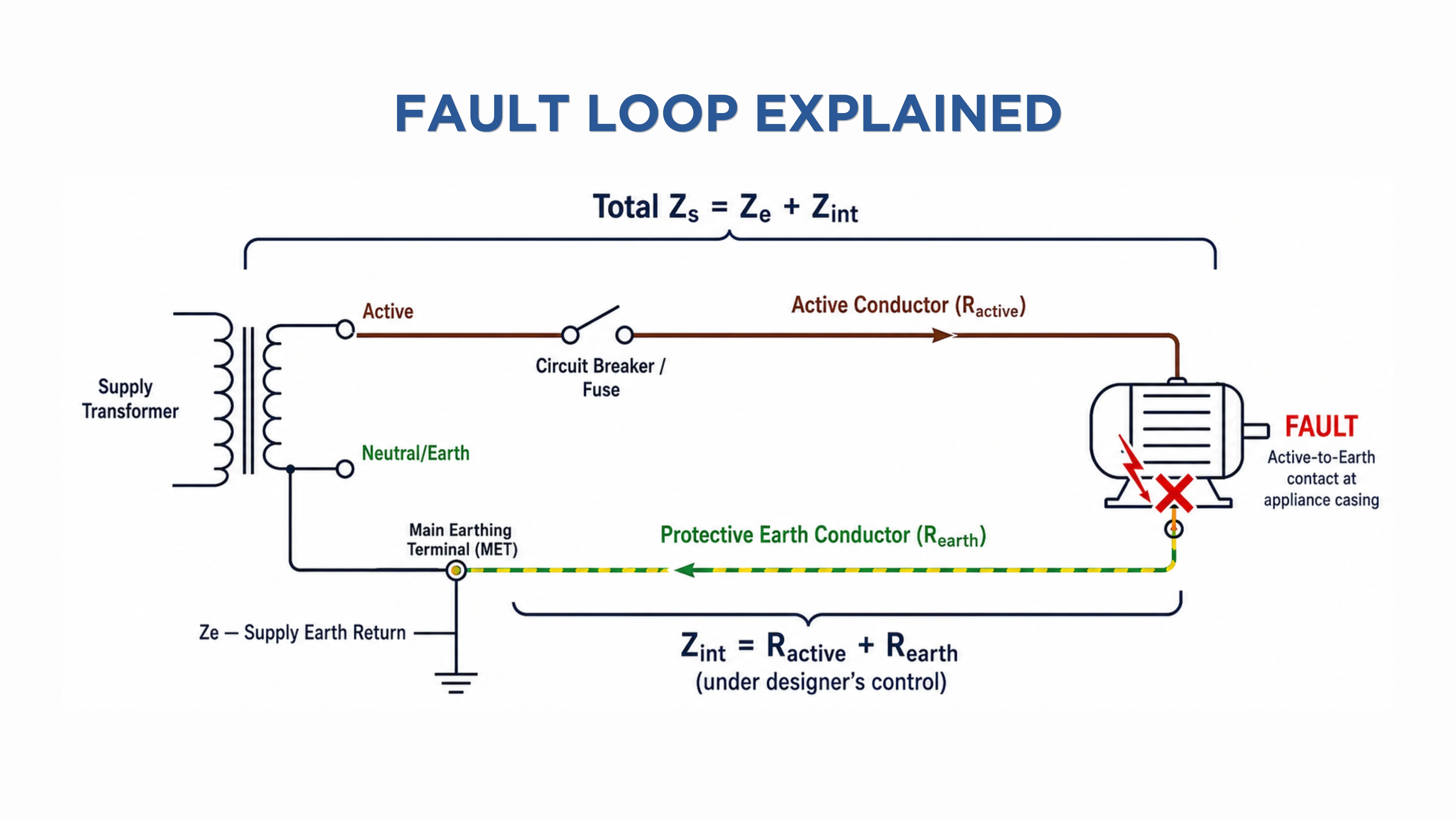
Fault loop impedance—abbreviated as Zs—is the total impedance of the path that fault current travels when an active conductor comes into contact with an earthed metal part.
When this fault occurs, current doesn't just disappear. It travels in a complete loop:
→ From the supply transformer
↓ through the active conductor
↓ to the fault point
↓ through the fault
↓ back through the protective earth conductor
↓ through the earthing arrangement
→ back to the transformer neutral
Every element in that path has resistance and/or reactance. The total is Zs which determines the amount of fault current:
Fault Current (If) = Supply Voltage (Uo) ÷ Fault Loop Impedance (Zs)
A lower Zs means higher fault current. Higher fault current means the circuit breaker or fuse operates faster. Faster operation means less time for current to flow through a person, and a lower risk of lethal shock or fire.
A higher Zs means lower fault current. Lower fault current means slower protective device operation or no operation at all. This is the failure mode that kills people and causes fires.CEdit.6.2.webp236.08 KB
How Does Zs Connect to Cable Sizing?
Fault loop impedance is a cable sizing constraint that must be considered at the design stage, alongside current-carrying capacity and voltage drop.
When you increase cable length, internal impedance increases proportionally. At some point, Zs = Ze + Zint will exceed Zmax for the chosen protective device. The circuit will not comply.
Fault loop impedance directly constrains the maximum circuit length for:
Cable size
Protective device type
Rated current
This is why AS/NZS 3000 and AS/NZS 3008 are used together: 3008 provides the conductor resistance and reactance data needed to calculate Zint accurately. The relationship works in both directions:
Longer circuit → Higher Zint → Higher Zs → May exceed Zmax → Upsize cable or change protective device
Smaller cable → Higher resistance per metre → Higher Zint → Same outcome
Designers who calculate voltage drop and current-carrying capacity, without verifying fault loop impedance, risk delivering an installation that looks correct but fails the safety requirement for automatic disconnection.
What Happens When Fault Loop Impedance Is Too High?
When Zs exceeds Zmax for the circuit's protective device, the fault current during an earth fault will be insufficient to trip the MCB or fuse within the required disconnection time.
This doesn't mean nothing happens. It means the protective device may trip slowly, or in some cases, not at all during the initial fault event. The practical consequences:
Electric shock hazard
Fire risk
Failed compliance
What Does the Fault Loop Consist of?
Understanding the loop is essential before you can calculate or test it correctly. The fault loop current path consists of:
The supply transformer winding
The supply cables from the transformer to the installation (the DNO's network)
The active (phase) conductor from the switchboard to the point of the fault
The fault itself (assumed to have negligible impedance for design purposes)
The protective earth (PE) conductor from the fault point back to the main earthing terminal (MET)
The earthing conductor from the MET back to the supply transformer neutral
This loop is divided into two parts for calculation purposes:
External impedance (Ze or Zext): The portion of the loop from the supply transformer to the installation's main earthing terminal (MET). This is fixed by the supply authority and the earthing system type and is outside the electrician’s control. This includes:
Transformer Winding Impedance
Supply Authority’s Network Cables
Supply Earthing
Internal impedance (Zint): The portion within the installation itself, from the main switchboard to the fault point and back through the earth conductor. This is the component the designer controls through cable sizing and includes:
Active conductor
Protective earth conductor for the specific circuit
What Is the Fault Loop Impedance Formula?
The total fault loop impedance is calculated as: Zs = Ze + Zint.
Zs = Total Fault Loop Impedance (Ω): The value that must be verified against the maximum permitted Zmax.
Ze = External impedance of the earth fault loop path from the supply to the MET (Ω): Typically assumed from network data or measured on site.
Zint = Internal impedance of the installation circuit, equal to the combined impedance of the active conductor and the protective earth conductor.
For circuit-level calculation, Zint is expressed as: Zint = R_active + R_earth.
R_active = Resistance of the active conductor
R_earth = Resistance of the protective earth conductor
Using AS/NZS 3008.1.1 resistance values (mΩ/m) for the conductor cross-section, material, and operating temperature: Zint = (ρ_active × L) + (ρ_earth × L).
ρ_active = Resistance per metre of the active conductor
ρ_earth = Resistance per metre of the protective earth conductor
L = One-way circuit length in metres
Determining Ze (External Impedance)
AS/NZS 3000 provides a useful simplification for Ze. The standard specifies that at least 80% of the nominal phase voltage must be available at the position of the protective device. For a 230 V single-phase supply, this means no more than 20% (46 V) can be lost in Ze.
Using this 80% rule: Ze (max) = (0.2 × Uo) ÷ If_min.
In practice, Ze for a typical Australian residential or commercial connection from a low-voltage distribution transformer is approximately 0.1 Ω to 0.35 Ω, depending on proximity to the transformer and network cable size. Where possible, measure Ze on site rather than relying on assumptions. Network characteristics vary significantly between locations.
The Maximum Fault Loop Impedance (Zmax)
For a protective device to operate within the required disconnection time, the actual Zs must be less than the maximum permitted value Zmax: Zmax = Uo ÷ Ia.
Uo = Nominal single-phase supply voltage
Ia = Current at which the protective device is guaranteed to operate within the required disconnection time
Ia depends on the protective device type, its rated current, and the required disconnection time. For MCBs, Ia is typically expressed as a multiple of rated current based on the trip curve:
Type B MCBs: Ia = 5× rated current (for 0.4 s disconnection)
Type C MCBs: Ia = 10× rated current (for 0.4 s disconnection)
Type D MCBs: Ia = 20× rated current (for 0.4 s disconnection)
For fuses, Ia values are taken from AS 60269.1 time-current characteristic data for the specific fuse type and rating. The calculated or measured Zs must always be less than Zmax for the installation to comply with AS/NZS 3000:2018.
What Are the AS/NZS 3000 Disconnection Time Requirements?
AS/NZS 3000:2018 sets two maximum disconnection time thresholds, and which one applies depends on the circuit type.
0.4 Seconds: Final Subcircuits
The maximum disconnection time for a 230/400 V supply is 0.4 seconds for:
Final subcircuits supplying socket outlets with rated currents less than 63 A
Equipment that is protectively earthed (Class 1 equipment)
Portable equipment that can be moved around during operation
The 0.4-second limit reflects the fact that portable and socket-outlet circuits are the most likely to be touched by someone during a fault. A person holding a faulty appliance or touching a faulty socket has no protection other than the speed of disconnection.
5 Seconds: Fixed and Stationary Equipment
The maximum disconnection time can be extended to 5 seconds where it can be demonstrated that people are not exposed to unsafe voltages while using the equipment. This applies to:
Submains feeding distribution boards
Circuits supplying stationary equipment that is not normally handled during operation
Industrial circuits where the equipment cannot be touched while energised
The practical effect: submains and distribution circuits can tolerate a higher Zs than final subcircuits, because the 5-second threshold requires lower fault current to achieve disconnection.
How Is Fault Loop Impedance Tested On Site?
AS/NZS 3000 requires testing during installation to verify earth fault loop impedance. The measured Zs must be equal to or less than the allowable Zmax for the protective device in use.
Method 1: Live Loop Impedance Test (Supply Available)
The standard method when the supply is energised:
Use a calibrated loop impedance tester
Connect between the active conductor and earth at the furthest point on the circuit
The instrument injects a brief current pulse and measures the total loop impedance
Record the result and compare against the maximum allowable Zs
The measured Zs must be less than or equal to the tabulated maximum for the protective device type, rating, and disconnection time requirement
Zs testing is conducted at ambient temperature, but the maximum tabulated values in AS/NZS 3000 are referenced at the cable's rated operating temperature.
Method 2: Dead Test (No Supply Available)
When no supply is available:
Connect the active conductor and the protective earth conductor together at the origin of the circuit (the switchboard end)
Measure the combined resistance of the active-earth loop using a calibrated ohmmeter at the furthest point of the circuit
Compare the result against Table 8.1 of AS/NZS 3000:2018, which provides maximum R1 + R2 values for various circuit types and protective devices
The dead test is inherently safer and is often preferred where RCDs would otherwise trip during live testing. All fault loop impedance test results must be recorded, including details of the test instrument used.
Calculate Fault Loop Impedance Confidently With CableHero
Fault loop impedance connects directly to how you size your cables. Get the conductor cross-section wrong and Zs may exceed Zmax before you discover the problem during commissioning.
CableHero is professional cable sizing software built specifically for Australian electricians and engineers. It includes fault loop and earth fault loop impedance calculators by allowing you to incorporate these into every cable sizing calculation from day one. With CableHero, you can:
Calculate Zint accurately using AS/NZS 3008.1.1 resistance and reactance values
Verify Zs against Zmax for the protective device type, rating, and disconnection time
Size earth conductors to satisfy both the fault loop impedance requirement and the adiabatic equation
Generate compliant PDF reports and cable schedules ready for certification and DNSP submission
Stop discovering fault loop impedance problems at commissioning. Design compliant circuits from the start. Check out CableHero for free today.
FAQ
What is fault loop impedance and why does it matter in Australian electrical installations?
Fault loop impedance (Zs) is the total impedance of the path that fault current travels when an active conductor contacts an earthed metal part. It is calculated as Zs = Ze + Zint, where Ze is the external supply impedance and Zint is the impedance of the installation's active and earth conductors.
How do you calculate the maximum allowable fault loop impedance?
The maximum allowable fault loop impedance is calculated using the formula Zmax = Uo ÷ Ia, where Uo is the nominal phase-to-earth voltage (230 V in Australia) and Ia is the current at which the protective device is guaranteed to operate within the required disconnection time.
What is the difference between Ze and Zs in fault loop impedance?
Ze (or Zext) is the external portion of the fault loop impedance—the impedance from the supply transformer to the installation's main earthing terminal. Zs is the total fault loop impedance for a specific circuit, calculated as Ze plus the internal impedance Zint.

 Cable Sizing

