- Step-by-Step Guide on Creating a Calculation
Step-by-Step Guide on Creating a Calculation #
To initiate a new cable run, follow our cable selection guide to keep you guided.
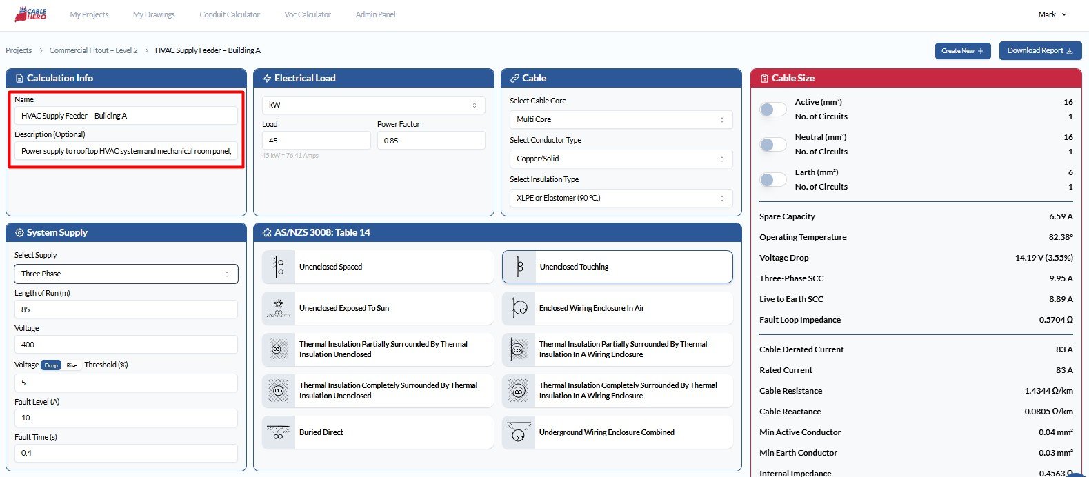
Step 1: Start a New Calculation #
First, enter the calculation details, including a clear name and description, to provide you a better context for your future review.
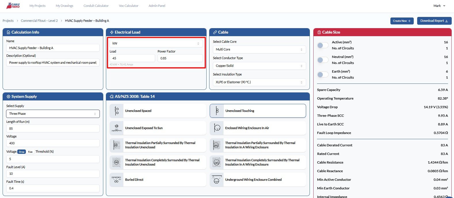
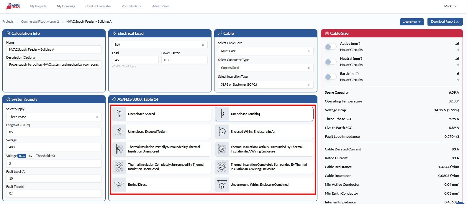
Step 2: Input Parameters #
Define key load and system input values such as unit of measure, load value and power factor.
- Unit of Measure: Choose from Amps, Watts, Kilowatts, or Horsepower (h.p.), depending on the nature of the load.
- Load Value: Enter the expected load value based on the chosen unit.
- Power Factor: Specify the power factor of the system, typically between 0.8 and 1.0 for AC systems.
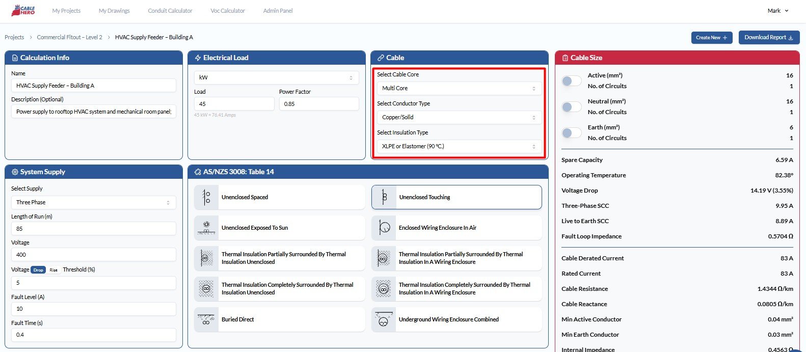
Step 3: Specify Cable Specifications #
Configure cable attributes to match design and environmental criteria:
- Number of Cores: Select between Single Core and Multicore configurations.
- Conductor Type: Choose from copper–solid, copper–flexible or Aluminium
- Insulation Type: The available options include Thermoplastic (75 °C), XLPE or Elastomer (90 °C.), Fire Rated (110 °C), Flexible Cords (60 °C) and Flexible Cords (150 °C).
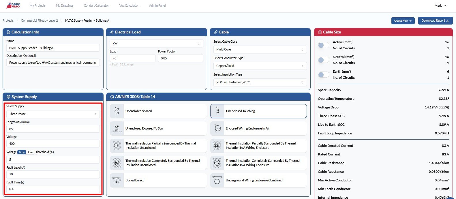
Step 4: Specify System Configuration #
Input system and environmental values to ensure accurate calculations:
- Supply Type: Choose between Single-phase, Three-phase, or DC.
- Cable Length: Specify the total cable run length in meters.
- Voltage System: Select the nominal voltage level (e.g., 230V, 400V).
- Voltage Drop/Rise: Enter the allowable percentage (e.g., ≤5%).
- Fault Level: Input the expected maximum fault current at the installation point.
- Fault Time: Define the protective device clearing time in seconds.
Step 5: Identify Installation Method #
Select the installation method that suits your project. Installation methods listed are based from AS/NZS 3008 – Table 4:
- Unenclosed Spaced
- Unenclosed Spaced from Surfaced
- Unenclosed Touching
- Unenclosed Exposed to Sun
- Enclosed Wiring Enclosure in Air
- Thermal Insulation Partially Surrounded By Thermal Insulation
- Thermal Insulation Completely Surrounded By Thermal Insulation
- Buried Direct
- Underground Wiring Enclosure Combined
- Underground Wiring Enclosure Separated
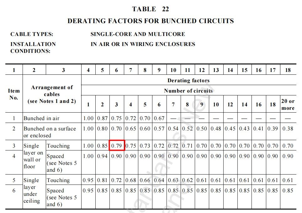
Step 6: Type in the Derating Factors #
Derating factors adjust the current-carrying capacity of cables based on installation environment, grouping, and thermal conditions. These adjustments are essential for safe, compliant derating cable designs and are guided by AS/NZS 3008 standards. The application of derating depends on whether the cable is installed aboveground or underground.
Aboveground Installation #
For aboveground setups, derating is primarily influenced by air temperature, grouping, and arrangement method. These conditions impact heat dissipation
Note: For reference, you can see the reference table from AS3008 under each section.
- Arrangement Type: Choose either Bunched or Cable Tray.
- Cable Tray Options: Unperforated Trays (Touching / Spaced), Perforated Trays (Touching / Spaced), Ladder Supports, Racks, Cleats (Touching / Spaced), Vertical
- Number of Rows: Specify the number of horizontal or vertical cable layers, especially when installed on trays.
- Cable Arrangement: In Air, On Surface or Enclosed, Single Layer on Wall (Touching / Spaced), Under Ceiling (Touching / Spaced)
- Number of Circuits: Indicate how many circuits are grouped together, as this affects heat dissipation.
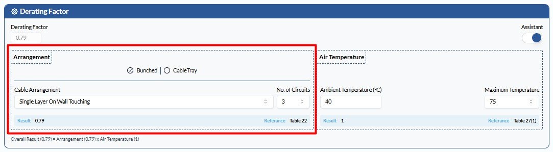
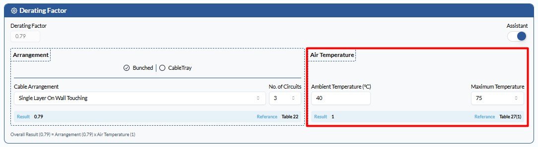
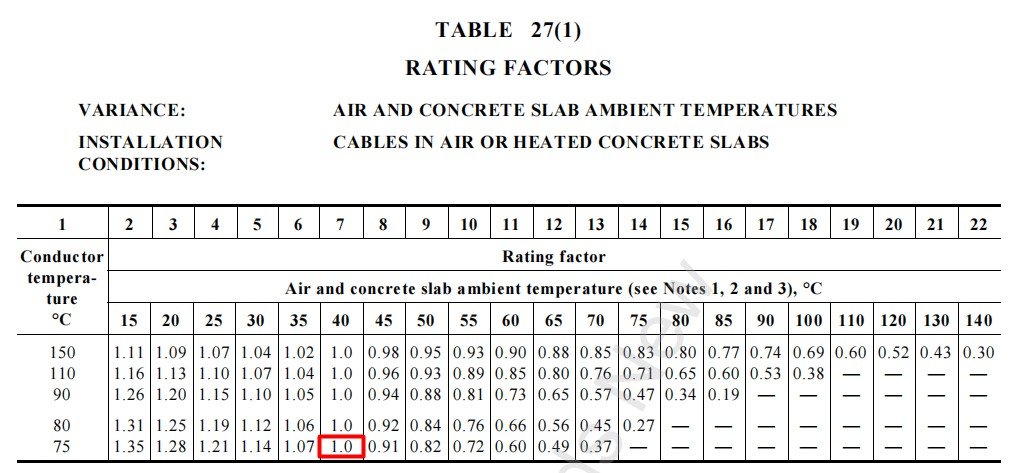
- Air Temperature: Input both ambient and maximum operating temperatures. These values are critical for applying accurate temperature correction factors based on AS/NZS 3008.
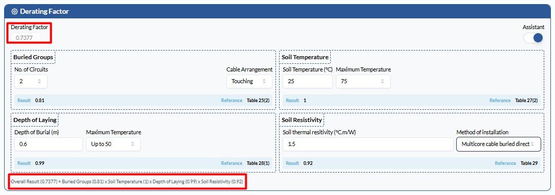
Underground Installation #
For underground configurations, thermal conditions and soil properties influence derating. Provide the following:
- Installation Type: Direct buried, in conduit, or enclosed trench.
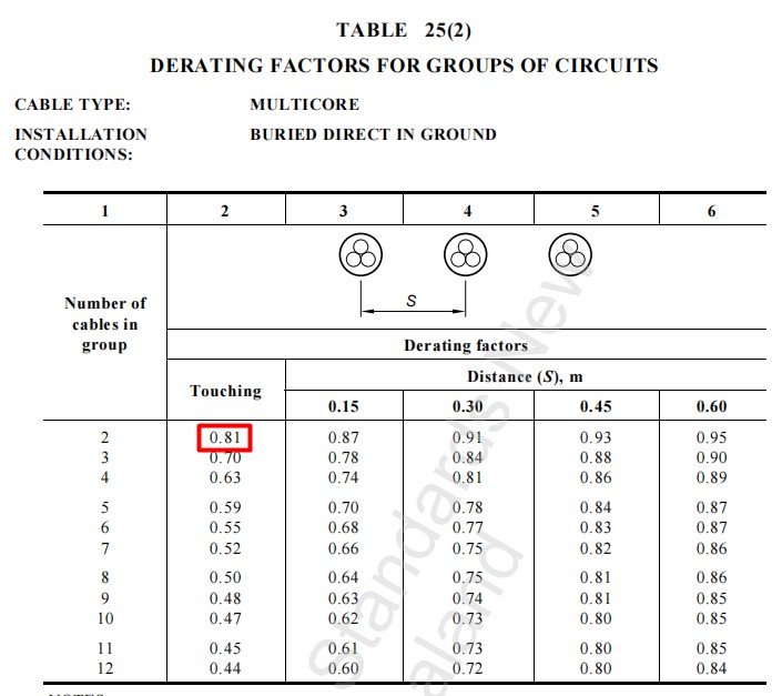
- Buried Groups: If multiple circuits are buried, define spacing or number of circuits in parallel.

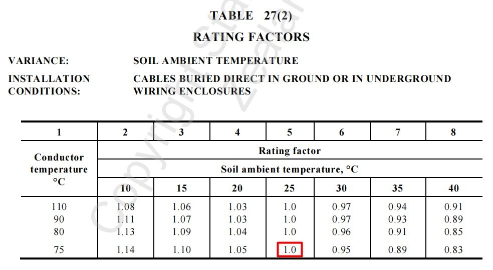
- Soil Temperature: Input the ambient soil temperature in °C, typically between 15°C and 35°C. Higher soil temperatures reduce the cable’s current-carrying capacity and trigger derating adjustments.
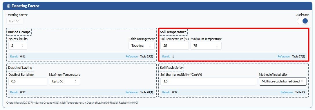
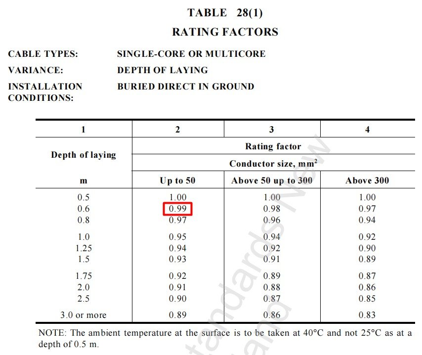
- Depth of Laying: Indicate how deep the cable is laid. Deeper burial can affect heat transfer and derating.
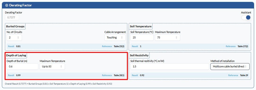
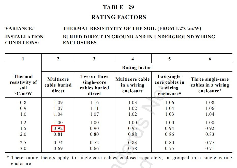
- Soil Resistivity: Enter the value in °C·m/W, typically ranging between 1.2 and 2.5.
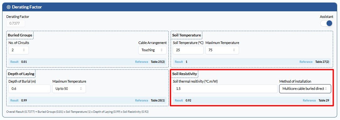
At the end of this section, you’ll see the overall derating factor. You’ll also see the breakdown of each applied derating factor at the bottom for easier viewing.
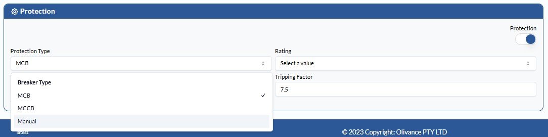
Step 7: Define Protection #
Check on the circuit protection to ensure proper fault-clearing behaviour.
1. Specify protection type (MCB, MCCB, manual) #
MCB (Miniature Circuit Breaker) #
commonly used for residential and light commercial applications. Required inputs are:
- Protection Type
- Rating
- Tripping Factor Type
- Tripping Factor
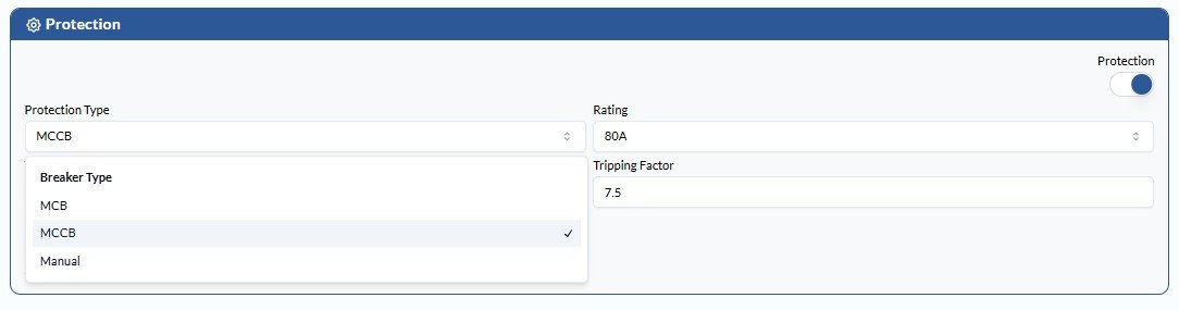
MCCB (Moulded Case Circuit Breaker) #
used for higher current circuits, typically in industrial and large commercial systems. Required inputs are:
- Protection Type
- Rating
- Tripping Factor Type
- Tripping Factor
- Manual Tripping Current
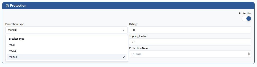
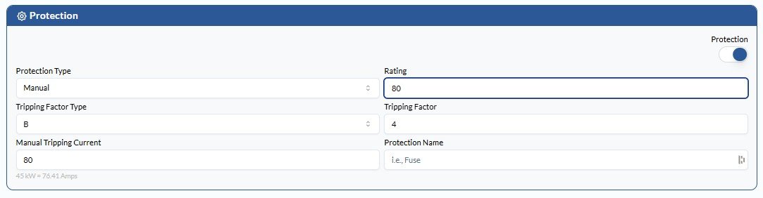
Manual (Manual Protection/Override Option) #
allows users to manually define protection for custom or non-standard scenarios.
- Protection Type
- Rating
- Tripping Factor Type
- Tripping Factor
- Manual Tripping Current
- Protection Name
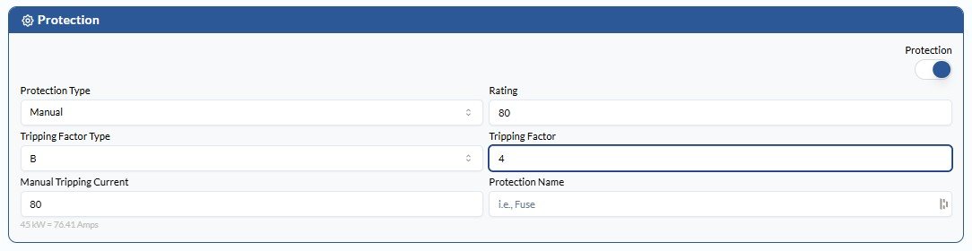
2. Select tripping factor type (e.g., B, C, D) #

3. Enter rating #
4. Input tripping factor value #
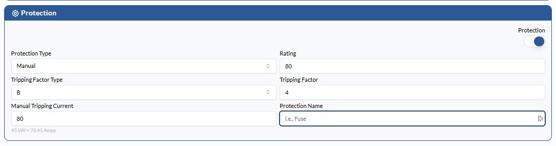
5. Add a protection name (optional) #
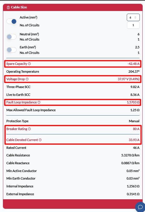
Step 8: Customise the Cable Size #
After entering all required parameters, CableHero automatically calculates and recommends the most suitable cable sizes for active, neutral, and earth conductors. The result displays a comprehensive set of performance values to support design verification and compliance, like:
- Spare Capacity
- Operating Temperature
- Voltage Drop
- Three-Phase Short-Circuit Current (SCC)
- Live to Earth Short-Circuit Current (SCC)
- Fault Loop Impedance
- Protection Type
- Breaker Rating
- Cable Derated Current
- Rated Current
- Cable Resistance
- Cable Reactance
- Minimum Active Conductor Size
- Minimum Earth Conductor Size
- Internal Impedance
- External Impedance
These values are automatically computed based on AS/NZS 3008 parameters, system inputs, and derating conditions, providing a reliable baseline for most design scenarios.
Where required, users can manually override the system-suggested cable size to accommodate project-specific design constraints, client specifications, or engineering judgement. This feature offers flexibility for tailoring cable selections while maintaining visibility over the technical impacts of any adjustments.
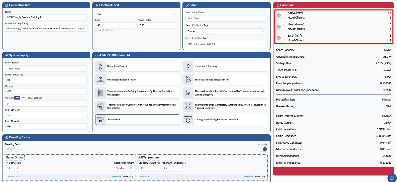
But it’s worth noting that if the manually overridden cable size does not meet the required standards or performance criteria, the affected results will be clearly highlighted in red. This visual cue indicates non-compliance or failure in one or more parameters, such as voltage drop, current-carrying capacity, or spare capacity.
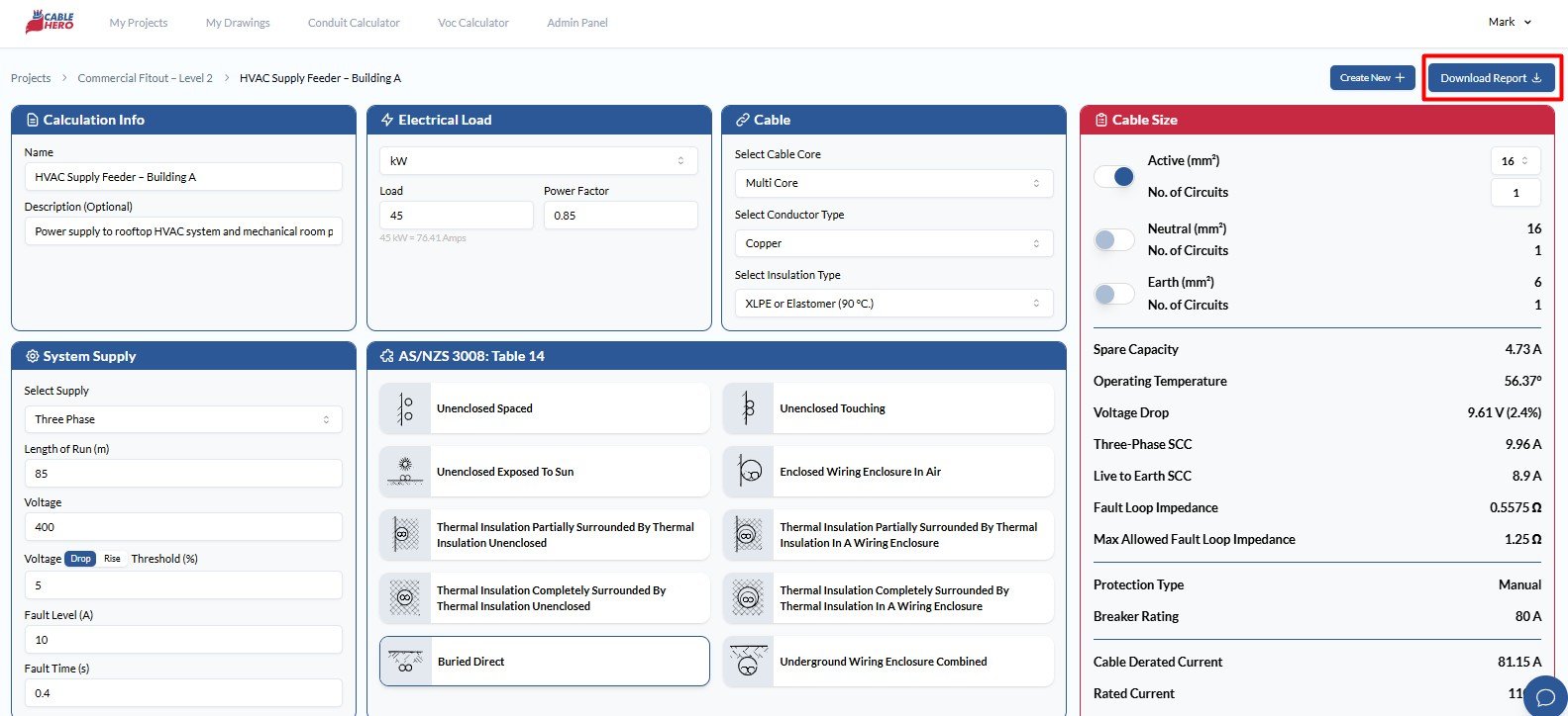
Step 9: Save and Export Results #
After inputting all the necessary information and completing your calculation, it’s time to:
- Save for Future Edits: Calculations are stored within your project and can be revisited or updated anytime.
- Export Formats: Generate a downloadable report in PDF format, suitable for documentation, compliance submission, etc.
As a whole, CableHero’s structured cable selection guide helps users through each critical input. With its user-friendly interface and robust technical framework, electrical professionals can deliver precise, reliable cable sizing with confidence. To learn more about our platform, contact us today!