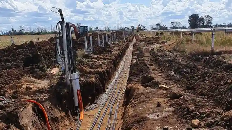
When planning underground electrical installations, selecting an appropriate cable size is necessary to maintain safe operating conditions. Cables must function below their current-carrying limits to prevent excessive heat buildup and reduce the risk of thermal failure.
With that said, this article explains how soil thermal resistivity influences underground cable performance by affecting heat dissipation into the surrounding ground. It also introduces practical tools, such as a cable sizing calculator, wire size calculator, and voltage drop calculator, that can support accurate cable selection during the design process.
What is Soil Thermal Resistivity?
It refers to the soil’s ability to resist the flow of electric current. It’s influenced by several factors, including soil composition, moisture content and retention, installation depth, the electrical load on the cable, and ambient temperature.
Among these, temperature has the most significant impact on resistivity. For this reason, accurately determining soil thermal resistivity is important before installing underground cables, as it directly affects temperature performance and long-term reliability.
AS/NZS 3008 Standards on Underground Cabling
The AS/NZS 3008.1.1:2017 Standard outlines the installation and operating conditions for two types of underground cabling: cables buried directly in the ground and cables installed within underground wiring enclosures. It provides guidance that can be applied effectively using a cable sizing calculator.
Conditions for Cables Buried Directly in the Ground
According to the Standard, the current-carrying capacities are dependent on the following factors:
- A 25°C ambient soil temperature.
- A 0.5m laying depth that’s measured from the ground surface to the centre of a cable, or to the centre of a trefoil arrangement of cables (3-phase system).
- A 1.2°C.m/W soil thermal resistivity.
- Cables to be spaced as:
- Single-core cables:
- 3 single-core cables laid touching throughout in a trefoil arrangement
- 2-3 single-core cables laid touching in a flat formation
- Singly laid multicore cables
- Single-core cables:
Conditions for cables in underground wiring enclosures
According to the Standard, the current-carrying capacities are dependent on the following:
- A 25°C ambient soil temperature.
- A 0.5m depth of laying measured from the ground surface to the centre of a cabling enclosure or to the centre of a trefoil arrangement of cabling enclosures (3-phase system).
- A 1.2°C.m/W soil thermal resistivity.
- Cabling enclosures to be spaced as:
- Single-core cables in individual cabling enclosures:
- With 2 ducts side by side touching
- 3 ducts in trefoil arrangement or in a flat formation touching
- Single-core cables as a circuit in one cabling enclosure
- Multicore cable in one cabling enclosure
- Single-core cables in individual cabling enclosures:
The Impact of Soil Thermal Resistivity
Soil thermal resistivity influences the current-carrying capacity of cables installed in underground wiring enclosures. The AS/NZS 3008 Standard adopts a default value of 1.2 °C·m/W, representing an average based on various soil types and conditions expected during peak loading.
In practice, however, soil thermal resistivity can vary widely due to factors such as soil composition, moisture content, ambient temperature, and installation depth. For this reason, it’s important to assess the thermal resistivity along the proposed cable route. The measured values should then be used with the rating factors in Table 29 of the AS/NZS 3008 Standard to ensure accurate cable sizing and safe long-term operation.
Simplify Your Projects with a CableHero
The AS/NZS 3008 Standard outlines detailed installation and operating conditions that should be followed when determining the current carrying capacity of underground cables. By accounting for soil thermal resistivity, ambient soil temperature, and laying depth, professionals can design systems that support safe and efficient cable performance.
Moreover, calculating the appropriate cable size for underground installations can be complex. However, tools like CableHero’s online cable size calculator make the process more manageable. Engineers and electricians can sign up for a free trial to explore the tool’s capabilities.
In addition to the cable sizing calculator, CableHero offers voltage drop calculators, wire size calculators, solar cable size calculators, and a conduit size calculator to support various aspects of electrical design. Try CableHero today and register for a free trial!
Disclaimer: While CableHero aims to provide accurate and helpful information on this website, it does not guarantee the completeness, accuracy, reliability, or timeliness of the content. Users are advised to exercise their own judgment, as CableHero assumes no liability for any outcomes from using the information provided.
Frequently Asked Questions (FAQs)
If you want to know more about soil thermal resistivity and how to size cables, check out these details:
How to calculate cable size?
Calculate cable size by determining the required current-carrying capacity based on the load and applying correction factors for installation conditions. Then select a cable with a cross-sectional area that meets or exceeds this adjusted current rating.
What happens if the wrong cable size is used in an underground installation?
Using an incorrectly sized cable can lead to overheating, voltage drop, and energy losses. Over time, this may result in insulation damage, reduced cable lifespan, and safety hazards such as electrical fires or system failure.
