
Single-line diagrams (SLDs) are simplified schematics that represent an electrical power distribution system using a single line to depict multiple conductors. They are fundamental to planning, installing, and maintaining electrical systems. For engineers and designers working under AS/NZS 3000, producing an accurate and compliant SLD ensures safety, system functionality, and regulatory approval.
In this article, it outlines effective methods for preparing SLDs that meet the technical and documentation requirements of the AS 3000 Wiring Rules.
What Makes a Single Line Diagram AS/NZS 3000-Compliant
To meet AS 3000 Wiring Rules standards, an SLD needs to represent the installation’s electrical configuration accurately. It should include the correct ratings and placements of all devices and conductors and show how electricity flows from the main switchboard through various protective devices, distribution boards, and final subcircuits.
Essential elements include:
- The type of supply (single-phase or three-phase)
- Voltage levels
- Overcurrent protection rating for each circuit
- Cable sizes and installation conditions
- Switchboards, isolators, and distribution boards
- Earthing and bonding arrangements
Relevant clauses from AS/NZS 3000 include:
- Clause 2.5 (Fault protection and disconnection)
- Clause 3.3 (Arrangement of final subcircuits)
- Clause 3.9 (Switchboard construction and layout)
These requirements should be technically represented and visually clear. It’s also important to use standardised symbols (e.g., from AS/NZS 60617) and maintain consistency throughout the diagram.
Step-by-Step Approach to Creating a Compliant SLD
The steps below outline how to define system parameters, apply protection and sizing standards, and document SLD installation accurately:
Assess the System Configuration
Begin by identifying whether the installation uses a single-phase or three-phase supply. Confirm the incoming supply voltage, maximum demand, and load distribution requirements. This foundational information determines the layout and scale of your SLD.
Select Appropriate Overcurrent Protection Devices
Choose protection devices based on load characteristics and fault conditions. The overcurrent protection rating should be appropriate for the load’s normal operating current and short-circuit withstand capacity.
Use time-current curves and manufacturer specifications to select devices such as Miniature Circuit Breakers (MCBs), Residual Current Devices (RCDs), or fuses. Ensure each device meets the disconnection time limits required by AS/NZS 3000, particularly 0.4 seconds for final subcircuits ≤32 A.
Determine How to Size Cables
Understanding how to size cables correctly requires a structured approach that balances current-carrying capacity, safety, and regulatory compliance:
Calculate the design current (Ib) using the formula:
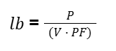
Where:
- lb = Design current (in amperes)
- P = Power (in watts)
- V = Voltage (in volts)
- PF = Power factor (typically between 0.8 and 1)
Select cables based on current-carrying capacity, installation conditions, and derating factors such as grouping, ambient temperature, and soil resistivity
Perform a voltage drop calculation using the formula:
Vd =I(Rcos + Xsin)L
Where:
- I = current (A)
- R = resistance of the conductor (Ω/km)
- X = reactance of the conductor (Ω/km)
- L = one-way length of the conductor (km)
- θ = phase angle (based on power factor)
Confirm that the fault loop impedance (Zs) is below the maximum allowable value listed in Appendix B of AS/NZS 3000.
Use a Cable Sizing Calculator to Support Cable Selection
Using a cable sizing calculator allows for efficient, repeatable, and standards-based validation of design parameters. These tools simplify the application of correction factors, calculate voltage drop, and verify fault loop impedance. By entering values such as cable type, length, and installation condition, you can quickly identify the correct cable size that meets AS/NZS 3000 and AS/NZS 3008 requirements.
Organise and Label the SLD Clearly
A technically correct SLD can still be ineffective if poorly presented. To avoid this:
- Text size and clarity: Ensure labels, circuit numbers, and load descriptions are legible and consistent.
- Drawing organisation: Use a logical flow from the main switchboard to distribution boards and final circuits. Maintain spacing to prevent clutter.
- Standard symbols: Apply AS/NZS 60617-approved symbols for components (switchboards, breakers, isolators, RCDs, etc.). Avoid mixing symbol styles from different standards.
- Consistency: Use the same font, line weights, and symbol sizes across the drawing to improve readability.
- Cross-referencing: Align the SLD with load schedules and panel layouts for verification.
Common Mistakes in Preparing SLDs
To help prevent design errors and safety risks, engineers should be aware of common mistakes encountered when preparing SLDs and understand how to address them per the AS 3000 Wiring Rules:
- Incorrect Overcurrent Protection Ratings: Failing to match protection devices to the calculated load and short-circuit conditions can result in disconnection times that exceed safety limits. This can be avoided by referring to device curves and ensuring coordination with the design current and fault levels.
- Improper Cable Sizing: Overlooking derating factors such as ambient temperature, grouping, or installation method can lead to undersized cables. Applying the structured sizing process in AS/NZS 3000 and verifying calculations with a cable sizing calculator helps maintain compliance.
- Omitting Earthing and Bonding Paths: Leaving out Multiple Earthed Neutral (MEN) links, earth electrodes, or bonding conductors results in incomplete and non-compliant SLDs. Always include these components explicitly, following AS/NZS 3000 earthing requirements.
- Unlabelled or Incomplete Circuits: Circuits without identifiers, device types, or load descriptions create ambiguity and increase error risk. Ensure each element is clearly labelled and cross-referenced to the load schedule.
Ensure Safety and Compliance with CableHero
Creating AS/NZS 3000-compliant Single-Line Diagrams requires accurate cable sizing, correct overcurrent protection ratings, and clear earthing and circuit layout documentation. Avoiding common issues such as undersized cables and unlabelled circuits is essential for safety and compliance. Each element should be calculated, verified, and presented using standard symbols.
Fortunately, CableHero’s online calculators, such as cable sizing and fault loop impedance calculators, make this process faster and more reliable. These tools apply AS 3000 Wiring Rules, validate voltage drop and Zs values, and factor in installation conditions so you can produce accurate, inspection-ready SLDs with greater efficiency and confidence. To get started, sign up for a free account today!
Frequently Asked Questions (FAQs)
If you want to know more about preparing compliant SLDs, check out the information below!
What is a single-line diagram?
A single-line diagram is a simplified schematic that shows how electrical power flows through a system using single lines and standard symbols. It helps engineers and electricians understand circuit layout, protection, and connectivity.
Is it necessary to show the MEN connection on an SLD?
Yes. To meet the earthing requirements of AS/NZS 3000 Clause 5.3, the MEN link should be clearly shown at the main switchboard. This ensures that fault current can return to the source and trigger protective device operation within time.