
Beyond matching conductor size to design current, correct cable sizing should also account for voltage drop limits and timely disconnection during fault conditions. A key parameter in achieving this is the fault loop impedance (Zs), which determines the effectiveness of circuit protection. In this article, we get to explain how to size cables with fault loop impedance in mind and outlines how to integrate Zs into your calculations.
How Fault Loop Impedance Affects Cable Sizing
Fault loop impedance (Zs) is the total impedance of the earth-fault current path, represented as the vector sum of resistance and reactance encountered by the fault current. It flows from the fault point through conductors and the earthing system back to the supply source. The total impedance affects the fault current magnitude and determines whether the protective device will operate within the required disconnection time.
To understand how to size cables correctly, you need to verify if the calculated fault loop impedance doesn’t exceed the maximum allowable value. So, if the loop impedance is too high, the resulting fault current may not sufficiently trigger the protective device promptly. As a result, it increases the risk of electric shock and equipment damage.
AS/NZS 3000 Requirements for Fault Loop Impedance
The Wiring Rules establish clear requirements for the automatic disconnection of supply during fault conditions. According to AS/NZS 3000 (disconnection-time requirements), the maximum disconnection time is 0.4 seconds for final subcircuits supplying socket-outlets rated up to 63 A.
This requirement also applies to hand-held equipment or portable equipment intended for manual movement. For other circuits (including submains or circuits supplying fixed/stationary equipment), the allowable disconnection time is up to 5 seconds.
In addition, the AS/NZS 3000 requires testing during installation to verify earth fault-loop impedance. The Wiring Rules contain tables of maximum allowable Zs values for protective devices corresponding to circuit parameters.
Calculations are used during design to ensure that selected protective devices and conductor sizes will or are expected to meet those limits under the required disconnection times. The measured Zs should be equal to or less than the allowable Zs for the protective device in use.
Technical Steps to Integrate Fault Loop Impedance in Cable Sizing
The following steps outline how to accurately incorporate fault loop impedance into cable sizing to ensure compliance and electrical safety:
Step 1: Calculate Load Current (Ib)
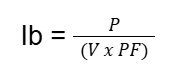
Begin by calculating the design current using the load power, voltage, and power factor. The formula is:
Where:
- lb = Design current (in amperes)
- P = Power (in watts)
- V = Voltage (in volts)
- PF = Power factor (typically between 0.8 and 1)
Include allowances for diversity, operating conditions, and equipment type as appropriate for the designed circuit.
Step 2: Select Protective Device
Choose a protective device that suits the application, such as a Miniature Circuit Breaker (MCB) or fuse. Refer to the manufacturer specifications or standard reference tables to identify the required disconnection time and maximum allowable Zs.
Step 3: Determine Maximum Allowable Zs
The maximum fault loop impedance is based on the protective device’s characteristics and its ability to disconnect the supply within the required timeframe. This value can be obtained from manufacturer data sheets or the AS/NZS 3000 appendix tables, specifically Appendix B (Maximum Values of Earth Fault Loop Impedance). Obtaining this value is important, as it becomes the upper limit for your fault loop impedance calculation.
Step 4: Perform Voltage Drop Calculation
Voltage drop should comply with Clause 3.6.2 of the Wiring Rules, which typically limits voltage drop to 5% of the nominal voltage for final subcircuits.
Use the following formula for voltage drop calculation:
Vd = I · (Rcos + Xsin) · L
Where:
- I = current (A)
- R = resistance of the conductor (Ω/km)
- X = reactance of the conductor (Ω/km)
- L = one-way length of the conductor (km)
- θ = phase angle (based on power factor)
Select resistance and reactance values based on the conductor material and installation temperature. Always apply temperature correction factors and account for grouping as required.
Step 5: Calculate Actual Fault Loop Impedance (Zs)
Once the preliminary cable size has been selected, calculate the actual fault loop impedance using the following formula:
Zs = Ze + (R1 + R2)
Where:
- Zs = fault loop impedance
- Ze = external fault loop impedance from the electricity distributor
- R1 = resistance of the line conductor
- R2 = resistance of the protective earth or neutral conductor
This calculation should include the conductors’ round-trip length. In addition to that, it’s just right to adjust resistance values to reflect the installation temperature and use corrected values from AS/NZS 3008 or cable manufacturer data.
Step 6: Validate Compliance
Once the actual fault loop impedance (Zs) has been calculated, compare it with the maximum allowable Zs identified in Step 3. If the calculated Zs are less than or equal to this limit, the circuit meets the fault protection requirements of AS 3000 Wiring Rules.
However, if the calculated Zs exceed the permissible value, corrective measures are necessary to bring the design into compliance. These may include increasing the conductor cross-sectional area to reduce resistance or shortening the overall circuit length to minimise impedance. Another option is to select a protective device with faster disconnection characteristics.
Using CableHero Calculators for Efficient Compliance
To simplify this process, CableHero provides two particularly useful calculators during the design phase:
Cable Sizing Calculator
This tool allows users to input design parameters such as load current, cable length, and installation conditions (e.g., grouping, ambient temperature, insulation type). It automatically performs a detailed voltage drop calculation based on standard conductor resistance and reactance values.
The calculator applies relevant derating factors per the Wiring Rules and returns a suggested cable size that satisfies current-carrying capacity and voltage drop limits.
Fault Loop Impedance Calculator
Once the preliminary cable size is selected, this calculator evaluates the total fault loop impedance. It considers factors such as cable length, conductor size, protective device type, disconnection curve, and the earth-fault loop impedance (Ze) supplied by the distribution network.
It confirms whether the actual Zs are within the maximum allowable limit defined in the Wiring Rules. If not compliant, the tool highlights corrective options such as increasing cable size or selecting a faster protective device.
Get Accurate Cable Sizing Calculations with CableHero
Understanding how to size cables correctly involves more than selecting a conductor based on load current; it also requires integrating fault loop impedance into the cable sizing process to meet the disconnection time requirements of AS/NZS 3000. The calculated Zs should align with the characteristics of the selected protective devices and remain within the allowable limits to ensure safe system performance.
By using CableHero’s cable sizing calculator, you can simplify the process, improve design accuracy, and confirm compliance. To get started, register for a free account today!
Frequently Asked Questions (FAQs)
Below are common questions that clarify how to size cables correctly while meeting safety, performance, and compliance requirements:
What is the maximum fault loop impedance?
The maximum fault loop impedance is the highest Zs value that still allows a protective device to disconnect within the required time. It depends on the device type, circuit rating, and system voltage, and is listed in AS/NZS 3000 Appendix B or device data sheets.
What causes high earth fault loop impedance?
High earth fault loop impedance is typically caused by long cable runs, undersized conductors, or poor earthing connections. These factors increase resistance in the fault path, which can delay protective device operation.